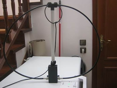
This is the mag loop that has been given by a ham radio operator, who
designed it 3 years ago and used not so often unless the weather was
good for outdoor reception .
In the start i will show several close up pictures of the so interesting loop which is actually a Faraday loop. The loop has been sent with all the parts packed in foam plastics to separate between.
The main loop has a circumference of ca 2 m and the secondary inductive loop is ca 40 cm and matches to the theory of Faraday loops This theory requires the secondary loop (Faraday loop ) to be the 1/5th of the main loop . It seems that the supporting tube is raltively smaller than the required making the loop in oval form but that really didn't matter as its job is really very good as far as it meets its specifications.
The above picture shows a close up of the small inductive Faraday loop. As you many see the joints of the loop made from RG58 cable are in reverse in order for the loop to work properly . What is not shown clearly here is that also on the top of the sec loop there is also another cut area from the shield asnd protected with insulating tape.
The guy did a great job to make this design with nice plastic
material for the axis including 'hratches' as we call the benders on the
top of the loop .
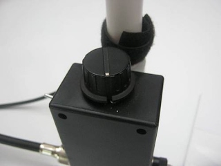
The above picture shows the capacitor base which is a muλti-turn double cap with a switch on the left upper part.
And this picture shows the base for the RG connector including a banana socket should the base be used for uses other than this loop . I used it once with the 1 m square loop.
And this picture shows the base for the RG connector including a banana socket should the base be used for uses other than this loop . I used it once with the 1 m square loop.
And this is the last picture of the mag loop showing the 'nippel'
adaptor system (fem to fem adaptor /bridge with two male plugs ) for
connecting to portable shortwave radios thru the 3.9 mm plug.
After this presentation i will notice my observations testing with several radios.
Range has been measured to be between 8900- 29000 kHz for the fist capacitor & 5350-10100 KHz with the second (approximate frequencies ±150 kHz). Notice that there is an overlapped band range.
Bandwidths vary and here are some examples:
For 16 MHZ the range is about 100 kHz
For 10 MHZ is at 40 kHZ
For 8.9 MHz is below 30 kHz ...........using the lone condenser
For 8.2 mHz is abt 200 kHz
For 6.8mHz nearly same (200 kHz )
For 5.6 MHZ about 50 kHz and less .............using both condensers
IN the overlapped band range I prefer to use the alone condenser
as the twin condenser setup offers lower Q (broader bandwidth)
This antenna as loop has the ability to null out interferences as
well as local noise (QRN) His is inw of the reasons i asked the
antenna from the radio amateur. The date i made this test there was not
any significant QRN as for example 3 weeks before , when a local
machine (?) caused a S7 noise across all the bands (as tested with R75
) that could not fully be nulled out.
Still this little QRN could be nulled out within 10 degs of turning the loop This has been tested with 1102 and 1103 directly connected via the cable My other 'cheap' small radios required a wire and female 3.5mm socket configuration to connect the one end to the ground and the other end to the antenna.Also a audio splitter is required to separate the ground for the earphone otherwise no audio could be heard!
In contrast to what i have been noticed the loop can be used also inductively with small radios:
1. with the radio's antenna to inductively couple over the loop.
1. with the radio's antenna to inductively couple over the loop.
2.
with a as thin as possible wire over the one part of the big loop that
can be then connected to the radio's antenna.This was my first on older
times and the last experiment these days with it. And seems to produce
very good results .
This idea on the older times didn't work , but if a radio was connected to the loop the above setup worked properly for remain radios. (all other radios that dont have plug socket ). I don't know if something happened to the cable but the loop seems operating properly .
The recent times the loop was used (last and this year ) seems to
work OK even a radio is not connected to it. The video below shows a
demo of this inductive coupling tough that time the antenna was
connected into the DE1103 radio
Verdict : 9/10 very good in its operation.
The only i don't know is to which wire length this design equals .The older times i had the idea to redesign this antenna to include lower frequencies. My interest is mainly between 4.5-15 MHz a good idea is to double the dimensions of this loop. The guy (radio amateur ) counter-proposed me to use a 3x1,5 mm cable (the typical cable for electricity connections) of ca 4 m length as loop and use the same capacitor system to tune it. I tested this idea with the 1 m loop but found no results ....
The only i don't know is to which wire length this design equals .The older times i had the idea to redesign this antenna to include lower frequencies. My interest is mainly between 4.5-15 MHz a good idea is to double the dimensions of this loop. The guy (radio amateur ) counter-proposed me to use a 3x1,5 mm cable (the typical cable for electricity connections) of ca 4 m length as loop and use the same capacitor system to tune it. I tested this idea with the 1 m loop but found no results ....
(NEW )BTW
with kudos to the designer he added me today that the idea of the
3x1.5mm2 cable (3 wind looped form )after the making can be inductively
coupled to the Faraday loop to be used for lower bands
the blue texte are the new additions
Unfortunately the loop was geting elder : the inner part of the Faraday loop has been cut and it was quite time consuming in my life to get it repaired> it can be rqiured either to get it redesign it again or just repair it. However with the adtition of mthe new SDR itbe not be use this way ..


No comments:
Post a Comment